
What Happens During the TULSA Procedure
1. Preparation
Before the procedure, the patient meets with his treatment team. Typically, the treatment team consists of a treating physican, an anestheislogist, and a Radiology Technologist. The treatment team ensures the patient is comfortable before sedation.
The patient then moves into the MRI room where the Ultrasound Applicator (UA) is inserted into the urethra, and the Endorectal Cooling Device (ECD) is inserted into the rectum by the treating physician.
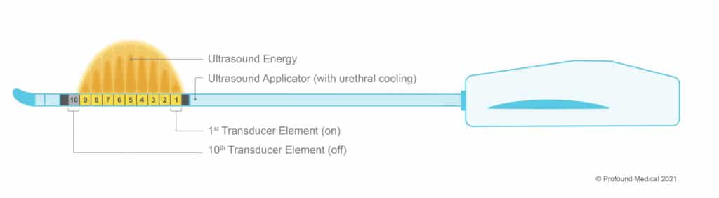
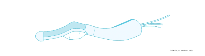
The UA has ten transducer elements - each one emits ultrasound energy in to the prostate. The physician can activate and control each transducer element depending on the prostate size. The UA also cools the urethra, which protects it from the thermal ultrasound energy. In the example below, only nine out of the ten transducer elements are needed to target the desired prostate tissue (Figure 1: The Ultrasound Applicator). The ECD is a passive cooling device that protects the rectal tissue from the thermal ultrasound energy, helping to preserve the patients natural functions (Figure 2: The Endorectal Cooling Device - ECD). There is no energy emitted by the ECD.
Once these devices are inserted into the patient, the treatment team is ready for the planning stage.
2. Planning
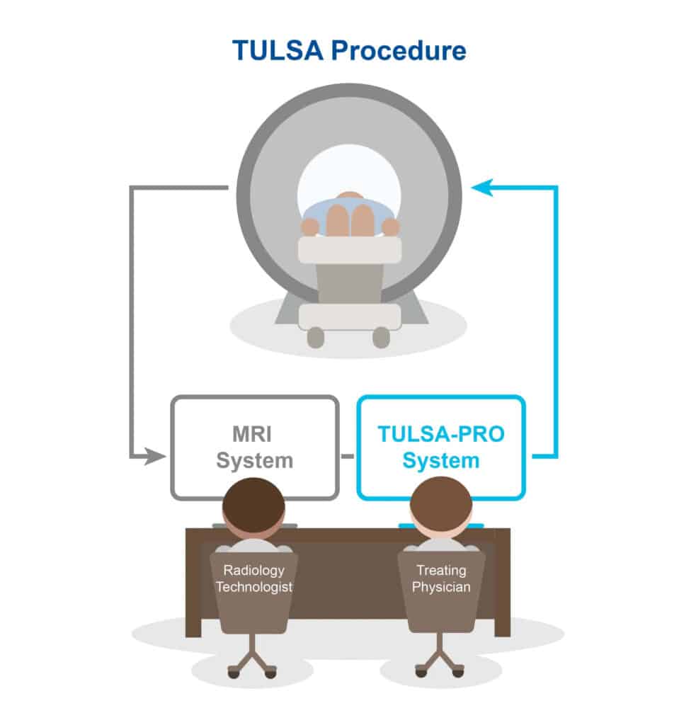
The TULSA Pro system is connected to the MRI machine. (Figure 3: The TULSA Procedure). This enables the physician to use high-precision MR imaging to determine the exact areas of the prostate that will be ablated. Using these MR images, the physician draws out the boundary lines to create the patient’s customized procedure plan, tailored to their individual prostate shape, size, and disease, while avoiding important nerve bundles and critical structures around the prostate.
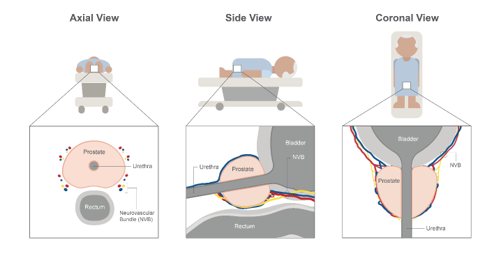
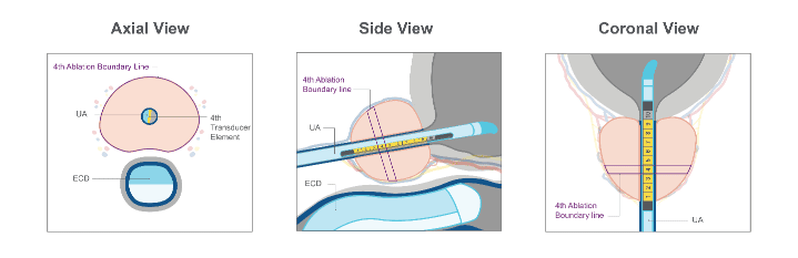
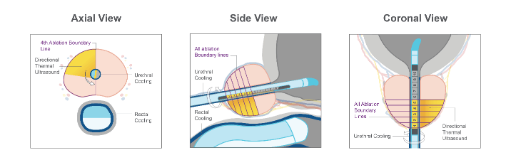
Using high-precision MR imaging, the physician can see the prostate in the axial view (Figure 4a), sagittal view (Figure 4b), and coronal view (Figure 4c). Using these images, the treating physician draws the boundary lines around the prostate section that corresponds to each ultrasound element. For example, in Figure 5, a specific ablation boundary line is drawn for transducer element 4. (Figure 4: The Prostate Anatomy in the a) axial view, b) side view, and c) coronal view). (Figure 5: The Ultrasound Applicator (UA), the Endorectal Cooling Device (ECD) and the boundary line for Transducer Element 4 in the a) axial, b) sagittal, and c) coronal view).
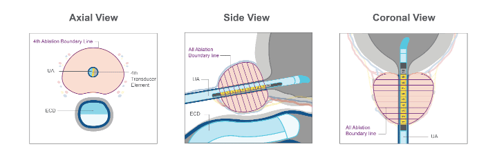
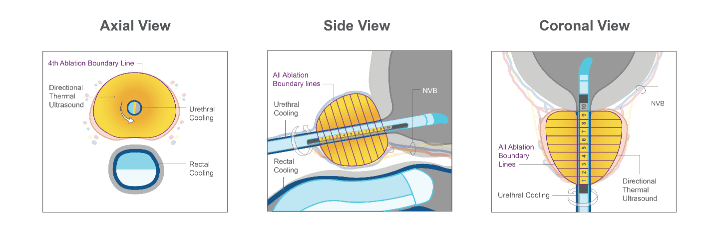
If the physician is preparing for a whole-gland ablation, they will continue to draw separate ablation boundary lines for the rest of the transducer elements, until the entire targeted prostate tissue region is selected (Figure 6). (Figure 6: Boundary lines for a whole-gland ablation procedure, with transducer elements 1-9 activated, in the a) axial, b) sagittal, and c) coronal view).
If the patient receives a partial gland ablation (for example a hemi ablation), the treating physician can customize the ablation area by drawing boundary lines around only sections of the prostate, and for only a subset of the transducer elements (Figure 7). (Figure 7: Boundary lines for a hemi ablation procedure, with transducer elements 1-5 activated, in the a) axial, b) sagittal, and c) coronal view).
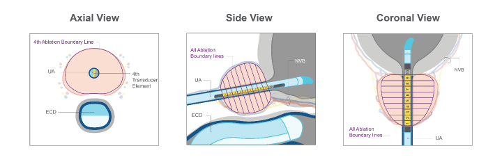
Some patients may be suitable for a nerve sparing plan, and the treating physician can accommodate this using the TULSA Procedure. The treating physician would adjust the ablation boundary lines so they are further away from the neurovascular bundles (Figure 8). (Figure 8: Boundary lines for a nerve sparing procedure, with transducer elements 2-9 activated, in the a) axial, b) sagittal, and c) coronal view).
The treating physician has the control and flexibility to adjust each boundary line depending on the patient’s anatomy (size and shape of prostate), their needs, and where the diseased prostate tissue is. Now that the boundary lines have been drawn, the treatment team is now ready to begin prostate ablation.

3. Delivery
During prostate ablation, the UA rotates within the urethra, creating a sweeping heating pattern that is directional and ablates the prostate tissue using an inside-out approach.
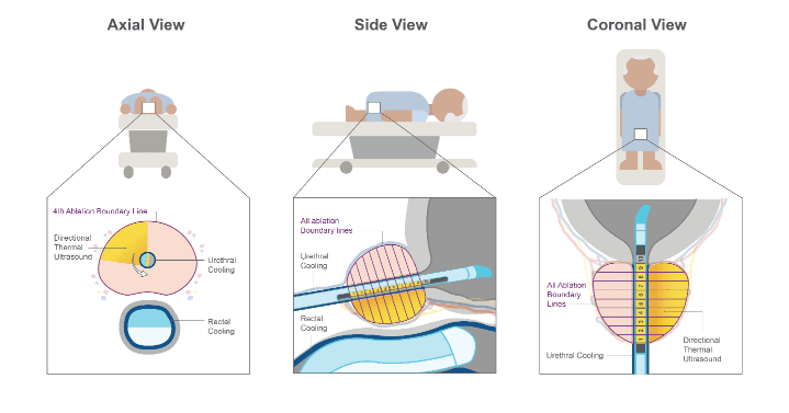
During the procedure, the TULSA-PRO system automatically carries out the ablation instructions outlined by the physician, ablating only within the prescribed boundary lines using real-time thermal images. The TULSA-PRO system carries out the physician’s treatment plan, which helps ensure precise prostate ablation and minimizes the risk of human error. (Figure 9: In this whole gland ablation, the physician can see the areas of the prostate being ablated in the a) axial view, b) side view, and c) coronal view.) (Figure 10: In this hemi ablation, the physician can see the areas of the prostate being ablated in the a) axial view, b) side view, and c) coronal view.)
TULSA PRO’s connection to the MRI machine creates a closed-loop thermal feedback system and allows for the physician to see MRI thermometry images in real-time. The real-time MRI thermometry images show the changing temperature of the prostate tissue and surrounding structures every 6 seconds. This visibility allows the physician to actively monitor tissue heating and make changes to the treatment delivery if necessary, making the TULSA Procedure controlled and predictable.
Once ablation is complete, the physician can always go back and deliver additional ablation to the prostate if necessary.
(Figure 11: In this nerve sparing ablation, the physician can see the areas of the prostate being ablated in the a) axial view, b) side view, and c) coronal view).
4. Confirmation
Using MR imaging, the physician will confirm the intended areas of the prostate that have been ablated successfully immediately after the procedure. Once the TULSA Procedure is complete, the patient will be catheterized and monitored during a brief recovery period. Patients are typically able to leave the same day, and resume daily activities.